
Technical Support
Installation And Safety
Installation Guidelines Safety Standards and Technical Information for BAKS Cable Routing
1. General Rules for Assembling BAKS Cable Routes
– use only screws recommended by the cable tray manufacturer for connections (details in respective chapters)
– use no fewer screws than recommended by the manufacturer for fastening (details in respective chapters)
– torque of screws and threaded rods must follow specifications
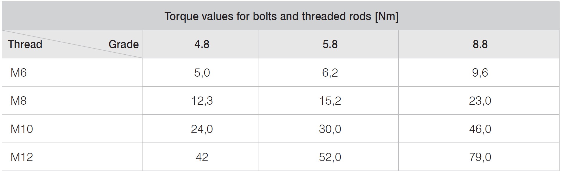
Table 1.1
– walking on installed cable trays is prohibited
– leaning on the sides of trays/ladders by installers, as well as loading cable routes with scaffolding or other construction elements during installation and operation, is prohibited
– placing heavy objects on the cable routes or mounting other installations on them is prohibited
– all elements of the cable route must be manufactured in a manner suitable for use in the designated corrosion class (details in the technical information)
– all cut edges must be protected against corrosion (details in the warranty)
– bolts should be inserted from the inside of the tray/ladder so that the nuts are on the outside of the side walls
2. Cable Trays, cable ladders, trunkings, profiles
2.1. Cable trays up to 1.2 mm thick – KG…, KC…, KB…, KO…, KL…
– connect by sliding one tray into another and fastening with SG…M6x… screw sets (details in Chapter I).
– the sidewalls of connected trays must be fastened with the maximum number of screw sets. Bottom connections depend on tray width:
50 – 75mm – 1 or 2 sets
100-200mm – 2 sets
300-400mm – 3 sets
500-600mm – 5 sets
– all used screw sets must be tightened to the torque specified in Table 1.1.
2.2. Cable Trays KA…, KCP…, KBP…
– butt-join the cable trays using connectors and internal connection plates (details in Chapter I)
– cable trays to be joined must be pushed together at the center of the connector and connection plate
– the joined cable trays must be fastened with the same number of SG…M6x… screw sets on both sides (details in Chapter I)
– all used screw sets must be tightened to the torque specified in Table 1.1.
2.3. Cable Trays KF „CLICK”
– join trays by placing the end of one tray over the other from above and snapping the latches. During assembly, ensure that the connection latches engage with the raised embossings
– for heavy loads, the “Click” connection can be fastened with screws (three SG…M6x… screw sets per side)
– the “Click” tray system includes all branching elements compatible with Click assembly (elbows, tees, bends, reducers)
– all used screw sets must be tightened to the torque specified in Table 1.1.
– the “Click” connection significantly speeds up cable tray assembly
2.4. Wall trunking
– wall trunking must be joined without screws using the LKS… connector (details in Chapter XVI)
– wall trunking must be pushed together at the center of the connector
2.5. Underfloor Trunking
– join trunking without screws using the compensating sleeve (details in Chapter XV)
– joined underfloor trunking must be pushed together at the center of the compensating sleeve
2.6. C-Profiles
– butt-join C-profiles using dedicated connectors (details in Chapter X)
– joined C-profiles must be pushed together at the center of the connector
– the joined C-profiles must be fastened with the same number of SG…M10x… screw sets on both sides (details in Chapter X)
– all used screw sets must be tightened to the torque specified in Table 1.1
2.7. Cable Ladders DK… and DU…
– butt-join ladders using LD… connectors (details in Chapter VI)
– joined ladders must be pushed together at the center of the connector
– the joined ladders must be fastened with the maximum number of SG…M8x… screw sets on both sides (details in Chapter VI)
– all used screw sets must be tightened to the torque specified in Table 1.1
2.8. Cable Ladders DF „CLICK”
– join cable ladders by placing the end of one ladder over the other from above and snapping the latches. When connecting DF “Click” ladders, ensure that the safety latch preventing
disengagement is seated in the hole.
– “Click” cable ladder system – the Click connection significantly speeds up cable tray assembly.
2.9. Long-span Cable Trays and Ladders Systems
– butt-join self-supporting trays and self-supporting ladders using dedicated connectors (details in Chapters III and VII)
– joined trays and ladders must be pushed together at the center of the connector
– joined self-supporting trays and ladders must be fastened with the maximum number of SG…M8x… screw sets on both sides (details in Chapters III and VII)
– all used screw sets must be tightened to the torque specified in Table 1.1
– the support structure must not obstruct the connection point of ladders or trays (on the connector)
2.10. Wire Mesh Cable Trays
– join wire mesh cable trays using USSN/USSO screw clamps (details in Chapter II)
– all used screw sets must be tightened to the torque specified in Table 1.1
2.11. KDSZ “Click” Wire Mesh Cable Trays
– join wire mesh trays by placing the end of one tray over the other from above and snapping the latches (details in Chapter II). After assembly, ensure that the connector sockets engage
the vertical wires on the sides of the connected tray.
– the “Click” connection significantly speeds up cable tray installation.
2.12. Marine System Trays
– join trays by sliding one into the other and fastening with SG…FM6x… screw sets (details in Chapter IX)
– all used screw sets must be tightened to the torque specified in Table 1.1
2.13. Marine System Ladders
– butt-join marine system ladders using LDOWH30 connectors (details in Chapter IX)
– joined ladders must be fastened with the same number of SG…FM8x… screw sets on both sides (details in Chapter IX)
– all used screw sets must be tightened to the torque specified in Table 1.1
2.14. Lighting System Trays
– KLWL75H60 cable trays are joined by sliding one into the other and fastening with five SG…M6x… screw sets (details in Chapter XVII)
– KLL75H60 cable trays are butt-joined using LPU1H60 connectors and 4 SG…M6x… screw sets per connector (details in Chapter XVII).
– joined cable trays must be pushed together at the center of the connector
– KLFL75H60 cable trays are joined by placing the end of one tray over the other from above and snapping the latches. During assembly, ensure that the connection latches engage
with the raised embossings
– all used screw sets must be tightened to the torque specified in Table 1.1
2.15. Machine Power Supply System
– butt-join trays using LKM…H… connectors and SG…M6x… screw sets (details in Chapter V)
– joined trays must be pushed together at the center of the connector
– joined trays must be fastened with the same number of SG…M6x… screw sets on both sides (details in Chapter V)
– all used screw sets must be tightened to the torque specified in Table 1.1
2.16. Fire-Resistant Cable Assemblies E30–E90
– cable trays and ladders forming part of fire-resistant cable assemblies must be joined according to the applicable National Technical Assessment (details in Chapter XIX)
– the shape of support structures and limit parameters of cable trays (support spacing, widths, loads, cable type and manufacturer, etc.) must comply with the applicable National
– technical Assessment (details in Chapter XIX)
– all used screw sets must be tightened to the torque specified in Table 1.1
– use of cable tray components from different manufacturers is not permitted (except for anchoring elements)
3. Support Structures
– support structures must be selected to withstand the loads on the tray route
– the spacing between support structures must ensure that the maximum allowable load for trays/ladders is not exceeded
– details on reading load charts for trays, ladders, and structural elements are included in the BAKS catalog
– exceeding the maximum allowable parameters of the cable trays (loads, support spacing, lengths, etc.) is prohibited
– cable trays and ladders must be securely fastened to support structures using dedicated clamps (details in Chapters XII and XIII)
– all screws and nuts used must be tightened to the torque specified in Table 1.1
Failure to follow the above guidelines/instructions in the cable tray installation manual will void any claims.
Detailed assembly information is provided on the catalog pages for each product, in examples at the end of sections, and in the detailed cable tray installation manual.
For any issues regarding cable tray installation, please contact BAKS Technical Support.
Safety Guidelines for Using BAKS Cable Routes
1. BAKS cable routes and their components are intended for routing and supporting power, telecom, pneumatic, water, and other cables. To ensure safe use, observe the following rules:
Cable trays must be properly designed and selected by qualified personnel experienced in electrical installations and, where applicable, licensed to design, paying special attention to product purpose, dimensions, allowable load, material, corrosive environment, etc.
Improper design or selection may pose a health and safety risk, cause malfunction, or damage the product.
2. Cable routes must be properly installed and grounded by qualified personnel experienced in electrical work. Improper installation or grounding may pose a health and safety risk, cause malfunction, or damage the product.
3. Cable routes must be inspected, serviced, and cleaned at intervals not exceeding 12 months by qualified personnel.
Failure to perform regular maintenance may pose a health and safety risk, cause malfunction, or damage the product.
4. Cable routes must not be used as walkways, climbing paths, or for hanging/transporting objects. Such use may cause collapse, endanger health and safety, and/or damage the product.
5. Cable routes must not be used for storing, installing, or suspending additional items or installations contrary to their intended purpose, e.g., during construction, installation, service, or renovation works. Such use and/or additional loading of the cable route may result in collapse, pose a risk to health and life, and/or lead to damage.